Tuesday, September 15, 2009

VIRTUAL VIEW


Power Plant Process


CFBC Boiler


Turbine


Generator


ELECTROSTATIC PRECIPITATOR


NATUARL DRAFT COOLING TOWER


INDUCED DRAFT COOLING TOWER


Monday, October 13, 2008

CHIMNEY


Chimney
A chimney is a system for venting hot flue gases or smoke from a boiler, stove, furnace or fireplace to the outside atmosphere. They are typically almost vertical to ensure that the hot gases flow smoothly, drawing air into the combustion through the chimney effect (also known as the stack effect). The space inside a chimney is called a flue. Chimneys may be found in buildings, steam locomotives and ships. In the US, the term smokestack (colloquially, stack) is also used when referring to locomotive chimneys. The term funnel is generally used for ship chimneys and sometimes used to refer to locomotive chimneys. Chimneys are tall to increase their draw of air for combustion and to disperse pollutants in the flue gases over a greater area so as to reduce the pollutant concentrations in compliance with regulatory or other limits.

History
Romans used tubes inside the walls to draw smoke out of bakeries but real chimneys appeared only in northern Europe in the 12th century. Industrial chimneys became common in the late 18th century.
chimneys were of a simple brick construction. Later chimneys were constructed by placing the bricks around tile liners. To control downdrafts venting caps (often called chimney pots) with a variety of designs are sometimes placed on the top of chimneys.


In the eighteenth and nineteenth centuries, the methods used to extract lead from its ore produced large amounts of toxic fumes. In the north of England, long near-horizontal chimneys were built, often more than 3 km (2 mi) long, which typically terminated in a short vertical chimney in a remote location where the fumes would cause less harm. Lead and silver deposits formed on the inside of these long chimneys, and periodically workers would be sent along the chimneys to scrape off these valuable deposits

Construction
Due to brick's limited ability to handle transverse loads, chimneys in houses were often built in a "stack", with a fireplace on each floor of the house sharing a single chimney, often with such a stack at the front and back of the house. Today's central heating systems have made chimney placement less critical, and the use of non-structural gas vent pipe allows a flue gas conduit to be installed around obstructions and through walls.
In fact, many modern high-efficiency heating appliances do not require a chimney. Such appliances are typically installed near an outside wall, and a noncombustible wall thimble allows vent pipe to be run directly through the outside wall.


Industrial chimneys are commonly referred to as flue gas stacks and are typically external structures, as opposed to being built into the wall of a building. They are generally located adjacent to a steam-generating boiler or industrial furnace and the gases are carried to it with ductwork. Today the use of reinforced concrete has almost entirely replaced brick as a structural component in the construction of industrial chimneys. Refractory bricks are often used as a lining, particularly if the type of fuel being burned generates flue gases containing acids. Modern industrial chimneys sometimes consist of a concrete windshield with a number of flues on the inside.


Flue gas stacks at Ekibastuz GRES-1 Power Plant in Ekibastuz, Kazakhstan are 330 metres tall
The 300 metre chimney at Sasol Three consists of a 26 metre diameter windshield with four 4.6 metre diameter concrete flues which are lined with refractory bricks built on rings of corbels spaced at 10 metre intervals. The reinforced concrete can be cast by conventional formwork or sliding formwork. The height is to ensure the pollutants are dispersed over a wider area to meet legislative or safety requirements.

Chimney tops


A chimney pot is placed on top of the chimney to inexpensively extend the length of the chimney, and to improve the chimney's draft. A chimney with more than one pot on it indicates that there is more than one fireplace on different floors sharing the chimney.
A chimney cap is placed on top of the chimney to prevent birds and squirrels from nesting in the chimney. They often feature a rain guard to keep rain from going down the chimney. A metal wire mesh is often used as a spark arrestor to minimize burning debris from rising out of the chimney and making it onto the roof. Although the masonry inside the chimney can absorb a large amount of moisture which later evaporates, rain water can collect at the base of the chimney. Sometimes weep holes are placed at the bottom of the chimney to drain out collected water.


Spanish Conquistador style wind directional cap found on many homes along the windy Oregon coast.
A chimney cowl or wind directional cap is helmet shaped chimney cap that rotates to align with the wind and prevent a back draft of smoke and wind back down the chimney.
A chimney damper is a metal spring door placed at the top of the chimney with a long metal chain that allows you to open and close the chimney from the fireplace.
In the late Middle Ages in Western Europe the design of crow-stepped gables arose to allow maintenance access to the chimney top, especially for tall structures such as castles and great manor houses.
Chimney draught or draft


The stack effect in chimneys: the gauges represent absolute air pressure and the airflow is indicated with light grey arrows. The gauge dials move clockwise with increasing pressure.

When coal, oil, natural gas, wood or any other fuel is combusted in a stove, oven, fireplace, hot water boiler or industrial furnace, the hot combustion product gases that are formed are called flue gases. Those gases are generally exhausted to the ambient outside air through chimneys or industrial flue gas stacks (sometimes referred to as smokestacks).
The combustion flue gases inside the chimneys or stacks are much hotter than the ambient outside air and therefore less dense than the ambient air. That causes the bottom of the vertical column of hot flue gas to have a lower pressure than the pressure at the bottom of a corresponding column of outside air. That higher pressure outside the chimney is the driving force that moves the required combustion air into the combustion zone and also moves the flue gas up and out of the chimney. That movement or flow of combustion air and flue gas is called "natural draught/draft", "natural ventilation", "chimney effect", or "stack effect". The taller the stack, the more draught or draft is created.
Designing chimneys and stacks to provide the correct amount of natural draught or draft involves a number design factors, many of which require trial-and-error reiterative methods.
As a "first guess" approximation, the following equation can be used to estimate the natural draught/draft flow rate by assuming that the molecular mass (i.e., molecular weight) of the flue gas and the external air are equal and that the frictional pressure and heat losses are negligible
where:

Q = chimney draught/draft flow rate, /s

A = cross-sectional area of chimney, (assuming it has a constant cross-section)

C = discharge coefficient (usually taken to be from 0.65 to 0.70)

H = height of chimney, m

Ti = average temperature inside the chimney, K

Te = external air temperature, K


Drawbacks
A characteristic problem of chimneys is they develop deposits of creosote on the walls of the structure when used with wood as a fuel. Some types of wood, such as pine, generate more creosote than others. Deposits of this substance can interfere with the airflow and more importantly, they are flammable and can cause dangerous chimney fires if the deposits ignite in the chimney. Thus, it is recommended — and in some countries even mandatory — that chimneys be inspected annually and cleaned on a regular basis to prevent these problems. The workers who perform this task professionally are called chimney sweeps. In the middle ages in some parts of Europe, a crow-stepped gable design was developed, partially to provide access to chimneys without use of ladders.


Masonry (brick) chimneys have also proved particularly susceptible to crumbling during earthquakes. Government housing authorities in quake-prone cities like San Francisco and Los Angeles now recommend building new homes with stud-framed chimneys around a metal flue. Bracing or strapping old masonry chimneys has not proved to be very effective in preventing damage or injury from earthquakes. Perhaps predictably, a new industry provides "faux-brick" facades to cover these modern chimney structures.
Other problems include "spalling" brick, in which moisture seeps into the brick and then freezes, cracking and flaking the brick and loosening mortar seals.


Dual-use chimneys
Some very high chimneys are used for carrying antennas of mobile phone services and low power FM/TV-transmitters. Special attention must be paid to possible corrosion problems if these antennas are near the exhaust of the chimney.
In some cases the chimneys of power stations are used also as pylons. However this type of construction is not very common, because of corrosion problems of conductor cables.
Cooling tower used as an industrial chimney
At some power stations, which are equipped with plants for the removal of sulfur dioxide and nitrogen oxides, it is possible to use the cooling tower as a chimney. Such cooling towers can be seen in Germany at the Power Station Staudinger Grosskrotzenburg and at the Power Station Rostock. At power stations that are not equipped for removing sulfur dioxide, such usage of cooling towers could result in serious corrosion problems.

BOILER

Boiler
A boiler is a closed vessel in which water or other fluid is heated. The heated or vaporized fluid exits the boiler for use in various processes or heating applications.
Application
Boilers have many applications. They can be used in stationary applications to provide heat, hot water, or steam for domestic use, or in generators and they can be used in mobile applications to provide steam for locomotion in applications such as trains, ships, and boats. Using a boiler is a way to transfer stored energy from the fuel source to the water in the boiler, and then finally to the point of end use.


Materials
Construction of boilers is mainly in steel, stainless steel, and wrought iron. In live steam models, copper or brass is often used. Historically copper was often used for fireboxes (particularly for steam locomotives), because of its better thermal conductivity. The price of copper now makes this impractical.
Cast iron is used for domestic water heaters. Although these are usually termed "boilers", their purpose is to produce hot water, not steam, and so they run at low pressure and try to avoid actual boiling. The brittleness of cast iron makes it impractical for steam pressure vessels.
For much of the Victorian "age of steam", the only material for boilermaking was the highest grade of wrought iron, with assembly by rivetting. This iron was often obtained from specialist ironworks, such as Cleator Moor (UK), noted for the high quality of their rolled plate and its suitability for high reliability use in critical applications, such as high pressure boilers. 20th century practice moved towards steel and welding.
Fuel
The source of heat for a boiler is combustion of any of several fuels, such as wood, coal, oil, or natural gas. Electric steam boilers use resistance or immersion type heating elements. Nuclear fission is also used as a heat source for generating steam. Heat recovery steam generators (HRSGs) use the heat rejected from other processes such as gas turbines.
Configurations
Boilers can be classified into the following configurations:
"Pot boiler" or "Haycock boiler": a primitive "kettle" where a fire heats a partially-filled water container from below. 18th Century Haycock boilers generally produced and stored large volumes of very low-pressure steam, often hardly above that of the atmosphere. These could burn wood or most often, coal. Efficiency was very low.

Fire-tube boiler. Here, water partially fills a boiler barrel with a small volume left above to accommodate the steam (steam space). The heat source is inside a furnace or firebox that has to be kept permanently surrounded by the water in order to maintain the temperature of the heating surface just below boiling point. The furnace can be situated at one end of a fire-tube which lengthens the path of the hot gases, thus augmenting the heating surface which can be further increased by making the gases reverse direction through a second parallel tube or a bundle of multiple tubes (two-pass or return flue boiler); alternatively the gases may be taken along the sides and then beneath the boiler through flues (3-pass boiler). In the case of a locomotive-type boiler, a boiler barrel extends from the firebox and the hot gases pass through a bundle of fire tubes inside the barrel which greatly increase the heating surface compared to a single tube and further improve heat transfer. Fire-tube boilers usually have a comparatively low rate of steam production, but high steam storage capacity. Fire-tube boilers mostly burn solid fuels, but are readily adaptable to those of the liquid or gas variety.
Water-tube boiler. In this type,the water tubes are arranged inside a furnace in a number of possible configurations: often the water tubes connect large drums, the lower ones containing water and the upper ones, steam; in other cases, such as a monotube boiler, water is circulated by a pump through a succession of coils. This type generally gives high steam production rates, but less storage capacity than the above. Water tube boilers can be designed to exploit any heat source including nuclear fission and are generally preferred in high pressure applications since the high pressure water/steam is contained within narrow pipes which can withstand the pressure with a thinner wall.
Flash boiler. A specialized type of water-tube boiler.
Fire-tube boiler with Water-tube firebox. Sometimes the two above types have been combined in the following manner: the firebox contains an assembly of water tubes, called thermic syphons. The gases then pass through a conventional firetube boiler. Water-tube fireboxes were installed in many Hungarian locomotives, but have met with little success in other countries.
Sectional boiler. In a cast iron sectional boiler, sometimes called a "pork chop boiler" the water is contained inside cast iron sections. These sections are assembled on site to create the finished boiler.
Superheated steam boilers


Most boilers heat water until it boils, and then the steam is used at saturation temperature (i.e., saturated steam). Superheated steam boilers boil the water and then further heat the steam in a superheater. This provides steam at much higher temperature, and can decrease the overall thermal efficiency of the steam plant due to the fact that the higher steam temperature requires a higher flue gas exhaust temperature. However, there are advantages to superheated steam. For example, useful heat can be extracted from the steam without causing condensation, which could damage piping and turbine blades.
Superheated steam presents unique safety concerns because, if there is a leak in the steam piping, steam at such high pressure/temperature can cause serious, instantaneous harm to anyone entering its flow. Since the escaping steam will initially be completely superheated vapor, it is not easy to see the leak, although the intense heat and sound from such a leak clearly indicates its presence.
The superheater works like coils on an air conditioning unit, however to a different end. The steam piping (with steam flowing through it) is directed through the flue gas path in the boiler furnace. This area typically is between 1300-1600 degrees Celsius (2500-3000 degrees Fahrenheit). Some superheaters are radiant type (absorb heat by radiation), others are convection type (absorb heat via a fluid i.e. gas) and some are a combination of the two. So whether by convection or radiation the extreme heat in the boiler furnace/flue gas path will also heat the superheater steam piping and the steam within as well. It is important to note that while the temperature of the steam in the superheater is raised, the pressure of the steam is not: the turbine or moving pistons offer a "continuously expanding space" and the pressure remains the same as that of the boiler.The process of superheating steam is most importantly designed to remove all droplets entrained in the steam to prevent damage to the turbine blading and/or associated piping.
Supercritical steam generators
Supercritical steam generators (also known as Benson boilers) are frequently used for the production of electric power. They operate at "supercritical pressure". In contrast to a "subcritical boiler", a supercritical steam generator operates at such a high pressure (over 3200 PSI, 22 MPa, 220 bar) that actual boiling ceases to occur, and the boiler has no water - steam separation. There is no generation of steam bubbles within the water, because the pressure is above the "critical pressure" at which steam bubbles can form. It passes below the critical point as it does work in the high pressure turbine and enters the generator's condenser. This is more efficient, resulting in slightly less fuel use and therefore less greenhouse gas production. The term "boiler" should not be used for a supercritical pressure steam generator, as no "boiling" actually occurs in this device.


History of supercritical steam generation
Contemporary supercritical steam generators are sometimes referred as Benson boilers. In 1922, Mark Benson was granted a patent for a boiler designed to convert water into steam at high pressure.
Safety was the main concern behind Benson’s concept. Earlier steam generators were designed for relatively low pressures of up to about 100 bar, corresponding to the state of the art in steam turbine development at the time. One of their distinguishing technical characteristics was the riveted drum. These drums were used to separate water and steam, and were often the source of boiler explosions, usually with catastrophic consequences. However, the drum can be completely eliminated if the evaporation process is avoided altogether. This happens when water is heated at a pressure above the critical pressure and then expanded to dry steam at subcritical pressure. A throttle valve located downstream of the evaporator can be used for this purpose.
As development of Benson technology continued, boiler design soon moved away from the original concept introduced by Mark Benson. In 1929, a test boiler that had been built in 1927 began operating in the thermal power plant at Gartenfeld in Berlin for the first time in subcritical mode with a fully open throttle valve. The second Benson boiler began operation in 1930 without a pressurizing valve at pressures between 40 and 180 bar at the Berlin cable factory. This application represented the birth of the modern variable-pressure Benson boiler. After that development, the original patent was no longer used. The Benson boiler name, however, was retained.
Two current innovations have a good chance of winning acceptance in the competitive market for once-through steam generators:
A new type of heat-recovery steam generator based on the Benson boiler, which has operated successfully at the Cottam combined-cycle power plant in the central part of England,
The vertical tubing in the combustion chamber walls of coal-fired steam generators which combines the operating advantages of the Benson system with the design advantages of the drum-type boiler. Construction of a first reference plant, the Yaomeng power plant in China, commenced in 2001.
Hydronic boilers
Hydronic boilers are used in generating heat typically for residential uses. They are the typical power plant for central heating systems fitted to houses in northern Europe (where they are commonly combined with domestic water heating), as opposed to the forced-air furnaces or wood burning stoves more common in North America. The hydronic boiler operates by way of heating water/fluid to a preset temperature (or sometimes in the case of single pipe systems, until it boils and turns to steam) and circulating that fluid throughout the home typically by way of radiators, baseboard heaters or through the floors. The fluid can be heated by any means...gas, wood, fuel oil, etc, but in built-up areas where piped gas is available, natural gas is currently the most economical and therefore the usual choice. The fluid is in an enclosed system and circulated throughout by means of a motorized pump. Most new systems are fitted with condensing boilers for greater efficiency. The name can be a misnomer in that, except for systems using steam radiators, the water in a properly functioning hydronic boiler never actually boils. These boilers are referred to as condensing boilers because they condense the water vapor in the flue gases to capture the latent heat of vaporization of the water produced during combustion.
Hydronic systems are being used more and more in new construction in North America for several reasons. Among the reasons are:
They are more efficient and more economical than forced-air systems (although initial installation can be more expensive, because of the cost of the copper and aluminum).
The baseboard copper pipes and aluminum fins take up less room and use less metal than the bulky steel ductwork required for forced-air systems.
They provide more even, less fluctuating temperatures than forced-air systems. The copper baseboard pipes hold and release heat over a longer period of time than air does, so the furnace does not have to switch off and on as much. (Copper heats mostly through conduction and radiation, whereas forced-air heats mostly through forced convection. Air has much lower thermal conductivity and higher specific heat than copper; however, convection results in faster heat loss of air compared to copper. See also thermal mass.)
They do not dry out the interior air as much.
They do not introduce any dust, allergens, mold, or (in the case of a faulty heat exchanger) combustion byproducts into the living space.
Forced-air heating does have some advantages, however. See forced-air heating.
Accessories
Boiler fittings and accessories
Safety valve: used to relieve pressure and prevent possible explosion of a boiler
Water level indicators: to show the operator the level of fluid in the boiler, a water gauge or water column is provided
Bottom blowdown valves provide a means for removing solid particulates that condense and lay on the bottom of a boiler. As the name implies, this valve is usually located directly on the bottom of the boiler, and is occasionally opened to use the pressure in the boiler to push these particulates out.
Hand holes are steel plates installed in openings in the boiler shell to allow for inspections of the interior of the boiler.
Low- water cutoff is a mechanical means (usually a float switch) that is used to turn off the burner or shut off fuel to the boiler to prevent it from running once the water goes below a certain point. If a boiler is "dry-fired" (burned without water in it) it can cause rupture or catastophic failure.
Surface blowdown line provides a means for removing foam or other lightweight non-condensible substances that tend to float on top of the water inside the boiler.
Circulating pump is designed to circulate water back to the boiler after it has expelled some of its heat.
Feedwater check valve or clack valve: a nonreturn stop valve in the feedwater line. This may be fitted to the side of the boiler, just below the water level, or to the top of the boiler. A top-mounted check valve is called a top feed and is intended to reduce the nuisance of limescale. It does not prevent limescale formation but causes the limescale to be precipitated in a powdery form which is easily washed out of the boiler.


Steam accessories
Main steam stop valve
Main steam stop/Check valve used on multiple boiler installations
Combustion accessories
Fuel oil system
Gas system
Coal system
Automatic combustion systems
Other essential items
Feed pumps
Inspectors test pressure gauge attachment
Name plate
Registration plate
Controlling draft

Most boilers now depend on mechanical draft equipment rather than natural draft. This is because natural draft is subject to outside air conditions and temperature of flue gases leaving the furnace, as well as the chimney height. All these factors make proper draft hard to attain and therefore make mechanical draft equipment much more economical.

There are three types of mechanical draft:

Induced draft: This is obtained one of three ways, the first being the "stack effect" of a heated chimney, in which the flue gas is less dense than the ambient air surrounding the boiler. The more dense column of ambient air forces combustion air into and through the boiler. The second method is through use of a steam jet. The steam jet oriented in the direction of flue gas flow induces flue gasses into the stack and allows for a greater flue gas velocity increasing the overall draft in the furnace. This method was common on steam driven locomotives which could not have tall chimneys. The third method is by simply using an induced draft fan (ID fan) which sucks flue gases out of the furnace and up the stack. Almost all induced draft furnaces have a negative pressure.
Forced draft: Draft is obtained by forcing air into the furnace by means of a fan (FD fan) and ductwork. Air is often passed through an air heater; which, as the name suggests, heats the air going into the furnace in order to increase the overall efficiency of the boiler. Dampers are used to control the quantity of air admitted to the furnace. Forced draft furnaces usually have a positive pressure.

Balanced draft: Balanced draft is obtained through use of both induced and forced draft. This is more common with larger boilers where the flue gases have to travel a long distance through many boiler passes. The induced draft fan works in conjunction with the forced draft fan allowing the furnace pressure to be maintained slightly below atmospheric.

POWER PLANT


A power station (also referred to as generating station or power plant) is an industrial facility for the generation of electric power.
Power plant is also used to refer to the engine in ships, aircraft and other large vehicles. Some prefer to use the term energy center because it more accurately describes what the plants do, which is the conversion of other forms of energy, like chemical energy, gravitational potential energy or heat energy into electrical energy. However, power plant is the most common term in the U.S., while elsewhere power station and power plant are both widely used, power station prevailing in many Commonwealth countries and especially in the United Kingdom.
At the center of nearly all power stations is a generator, a rotating machine that converts mechanical energy into electrical energy by creating relative motion between a magnetic field and a conductor. The energy source harnessed to turn the generator varies widely. It depends chiefly on what fuels are easily available and the types of technology that the power company has access to.
Thermal power stations


Rotor of a modern steam turbine, used in power station
Main article: Thermal power station
In thermal power stations, mechanical power is produced by a heat engine, which transforms thermal energy, often from combustion of a fuel, into rotational energy. Most thermal power stations produce steam, and these are sometimes called steam power stations. About 80% of all electric power is generated by use of steam turbines.[citation needed] Not all thermal energy can be transformed to mechanical power, according to the second law of thermodynamics. Therefore, there is always heat lost to the environment. If this loss is employed as useful heat, for industrial processes or district heating, the power plant is referred to as a cogeneration power plant or CHP (combined heat-and-power) plant. In countries where district heating is common, there are dedicated heat plants called heat-only boiler stations. An important class of power stations in the Middle East uses byproduct heat for desalination of water.


Thermal power plants are classified by the type of fuel and the type of prime mover installed.
By fuel
Nuclear power plants use a nuclear reactor's heat to operate a steam turbine generator.
Fossil fuelled power plants may also use a steam turbine generator or in the case of natural gas fired plants may use a combustion turbine.
Geothermal power plants use steam extracted from hot underground rocks.
Renewable energy plants may be fuelled by waste from sugar cane, municipal solid waste, landfill methane, or other forms of biomass.
In integrated steel mills, blast furnace exhaust gas is a low-cost, although low-energy-density, fuel.
Waste heat from industrial processes is occasionally concentrated enough to use for power generation, usually in a steam boiler and turbine.
By prime mover
Steam turbine plants use the dynamic pressure generated by expanding steam to turn the blades of a turbine. Almost all large non-hydro plants use this system.
Gas turbine plants use the dynamic pressure from flowing gases to directly operate the turbine. Natural-gas fuelled turbine plants can start rapidly and so are used to supply "peak" energy during periods of high demand, though at higher cost than base-loaded plants.
Combined cycle plants have both a gas turbine fired by natural gas, and a steam boiler and steam turbine which use the exhaust gas from the gas turbine to produce electricity. This greatly increases the overall efficiency of the plant, and many new baseload power plants are combined cycle plants fired by natural gas.
Internal combustion Reciprocating engines are used to provide power for isolated communities and are frequently used for small cogeneration plants. Hospitals, office buildings, industrial plants, and other critical facilities also use them to provide backup power in case of a power outage. These are usually fuelled by diesel oil, heavy oil, natural gas and landfill gas.
Microturbines, Stirling engine and internal combustion reciprocating engines are low cost solutions for using opportunity fuels, such as landfill gas, digester gas from water treatment plants and waste gas from oil production.
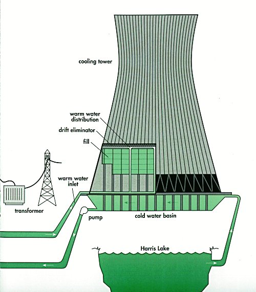
Cooling towers
All thermal power plants produce waste heat as a byproduct of the useful electrical energy produced. Natural draft wet cooling towers at nuclear power plants and at some large thermal power plants are large hyperbolic chimney-like structures that release the waste heat to the ambient atmosphere by the evaporation of water

A Marley mechanical induced-draft cooling tower
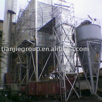
However, the mechanical induced-draft or forced-draft wet cooling towers (as seen in the image to the right) in many large thermal power plants, petroleum refineries, petrochemical plants, geothermal, biomass and waste to energy plants use fans to provide air movement upward through downcoming water and are not hyperbolic chimney-like structures. The induced or forced-draft cooling towers are rectangular, box-like structures filled with a material that enhances the contacting of the upflowing air and the downflowing water.


In desert areas a dry cooling tower or radiator may be necessary, since the cost of make-up water for evaporative cooling would be prohibitive. These have lower efficiency and higher energy consumption in fans than a wet, evaporative cooling tower.
Where economically and environmentally possible, electric companies prefer to use cooling water from the ocean, or a lake or river, or a cooling pond, instead of a cooling tower. This type of cooling can save the cost of a cooling tower and may have lower energy costs for pumping cooling water through the plant's heat exchangers. However, the waste heat can cause the temperature of the water to rise detectably. Power plants using natural bodies of water for cooling must be designed to prevent intake of organisms into the cooling cycle. A further environmental impact would be organisms that adapt to the warmer plant water and may be injured if the plant shuts down in cold weather.
In recent years, recycled wastewater, or grey water, has been used in cooling towers

Other power stations use the energy from wave or tidal motion, wind, sunlight or the energy of falling water, hydroelectricity. These types of energy sources are called renewable energy.
Hydroelectricity


Pumped storage

A pumped storage hydroelectric power plant is a net consumer of energy but decreases the price of electricity. Water is pumped to a high reservoir during the night when the demand, and price, for electricity is low. During hours of peak demand, when the price of electricity is high, the stored water is released to produce electric power. Some pumped storage plants are actually not net consumers of electricity because they release some of the water from the lower reservoir downstream, either continuously or in bursts.
Solar


A solar photovoltaic power plant converts sunlight into electrical energy, which may need conversion to alternating current for transmission to users. This type of plant does not use rotating machines for energy conversion. Solar thermal electric plants are another type of solar power plant. They direct sunlight using either parabolic troughs or heliostats. Parabolic troughs direct sunlight onto a pipe containing a heat transfer fluid, such as oil, which is then used to boil water, which turns the generator. The central tower type of power plant uses hundreds or thousands of mirrors, depending on size, to direct sunlight onto a receiver on top of a tower. Again, the heat is used to produce steam to turn turbines. There is yet another type of solar thermal electric plant. The sunlight strikes the bottom of the pond, warming the lowest layer which is prevented from rising by a salt gradient. A Rankine cycle engine exploits the temperature difference in the layers to produce electricity. Not many solar thermal electric plants have been built. Most of them can be found in the Mojave Desert, although Sandia National Laboratory, Israel and Spain have also built a few plants.

Wind

Wind turbine in front of a thermal power station in Amsterdam, Netherlands
Wind turbines can be used to generate electricity in areas with strong, steady winds. Many different designs have been used in the past, but almost all modern turbines being produced today use a three-bladed, upwind design. Grid-connected wind turbines now being built are much larger than the units installed during the 1970s, and so produce power more cheaply and reliably than earlier models. With larger turbines (on the order of one megawatt), the blades move more slowly than older, smaller, units, which makes them less visually distracting and safer for airborne animals. However, the old turbines can still be seen at some wind farms, particularly at Altamont Pass and Tehachapi Pass.

Operations

The power station operator has several duties in the electrical generating facility. Operators are responsible for the safety of the work crews that frequently do repairs on the mechanical and electrical equipment. They maintain the equipment with periodic inspections and logs temperatures, pressures and other important information on regular intervals. Operators are responsible for starting and stopping the generators depending on need. They are able to synchronize and adjust the voltage output of the added generation with the running electrical system without upsetting the system. They must know the electrical and mechanical systems in order to troubleshoot problems in the facility and add to the reliability of the facility. Operators must be able to respond to an emergency and know the procedures in place to deal with it.